This is part 2 of the mill DRO installation, covering the Y and Z axis. Refer to Adding a DRO to a Grizzly Mill – Part 1 for part 1.
Y Axis Approach & Installation
The Y axis is more involved as the area available for the scale is on the base, farther away from the Y stage. This entails a greater reach and more complicated method for a rigid connection from the stage to the read head. To minimize the reach, I decided to mount the scales as high on the mill base as possible, which then drove the need to make my own scale covers as the included covers were overly tall and wide. Drill access to the Y stage is limited. This set the vertical position of the M4 mounting holes.
Start by positioning the scale on the base, and confirm the read head is within the Y stage travel limits. Mark the scale mount holes and the holes for the Y stage bracket. Drill and tap for M4 bolts.
I then cut one of the included brackets down to keep it as close to the scale as possible. Mount it to the read head.
Mount the scale using bushings in the back to add 1 mm of clearance for the read head.
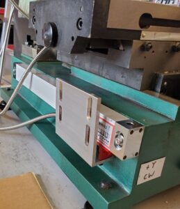
Level the scale.
Now the distance from the Y stage to the upper bracket can be precisely determined. Make sure the bracket is vertical and the read head angle is correct. This measurement is used as a critical dimension for a custom 3D printed part to connect the Y stage to the bracket.
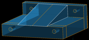
It includes a gusset to maximize rigidity in the Z direction.
Install M4 threaded inserts using a soldering iron and M4 insert tip. Make sure they are slightly below flush.
Attach it to Y stage, then the bracket.
Attach the scale cable to the display and run the Y stage over the range of travel and confirm everything is level and reading accurately. I had 2 mm of lateral skew in the stage relative to the base which required different shim thicknesses on the back side of the scales to eliminate the skew.
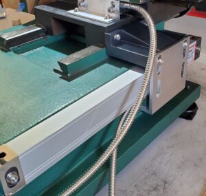
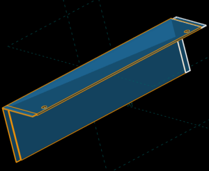
The final step for this axis is designing and 3D printing a cover. The length needed exceeds my printer’s max 256 mm size, so the covers are designed to interlock with eachother.
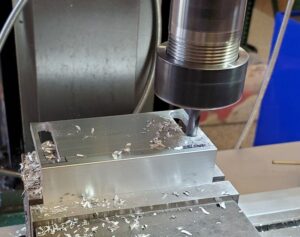
Drill and tap M4 mounting holes.
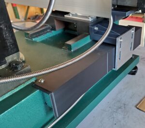
Install the covers.
Z Axis Approach & Installation
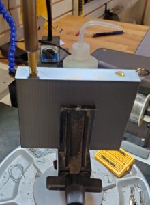
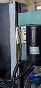
For simplicity, I decided to mount the scale to the tower sheet metal enclosure. Removal of this looked like too much trouble with the motor connections. The main issue was clearance between the enclosure and the mill Z head assembly. I went with M4 hex bolts as the head is slim and they can be wrenched from the side.
To install, I removed the enclosure bolts to get enough wiggle room and installed them from the inside.
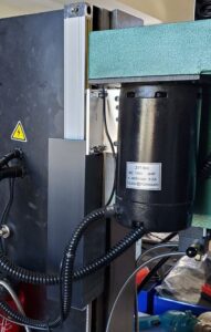
Mount the scale.
The slots were extended on one of the included brackets to reach the mounting holes on the bottom of the read head.
Attach the bracket to the read head and locate holes for mounting on the mill Z head. Remove the bracket, drill and tap M4 mounting holes.
Re-attach the bracket. Level the scale relative to the Z axis. The bushings were modified to provide some lateral travel.
Connect the scale cable to the display and verify the readings over the range of Z travel.
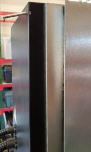
Lastly, a custom scale cover was designed.
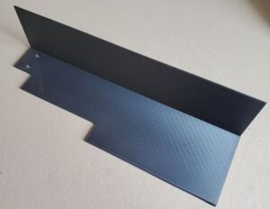
The attached cover.
Harnessing
For now, I slapped some magnet hooks on the mill and am strain relieving the cables along these.
As for power, everything on the mill is routed to a surge protected plug strip mounted under the table. Especially with sensitive electronics like this, I shut off the entire plug strip when the mill is not in use.
Summary
It’s so nice having a digital readout now. Not sure I need some of the fancier features of the display, time will tell.
Models for all custom 3D printed parts created for this project can be found at Printables.