I’ve had a Grizzly manual mill for years and it was time to extend milling to include CNC. I didn’t want to hassle with modifying the Grizzly mill, nor am I ready to get a high end quarter ton setup.
CNC Selection
I decided to look into something more entry level, with enough power to mill aluminum, and preferably steel.
I researched every manufacturer I could find, with the shortlist being Anolex, the Carvera (very cool, with auto tool change, but underpowered and 4x the cost) and ShapeOko 4 (lower end drive system, no laser etch option, 2x the cost).
The Anolex stood out in a number of areas. First, the quality of the design and materials used appear to be top notch. The Anolex controller is grbl based. This open source based system is more appealing, eliminating vendor lock in and widening the choices for GCode senders.
Anolex offers several models, and I went with the highest end 4030 Evo Ultra. Some of the reasons for choosing this vs the 3030 Pro include:
– 500W spindle: this is a big step up from the 3030 Pro and hopefully defer the need for higher end spindle a la the typical Makita router upgrade.
– upgraded drive system.
– built in ESP32 with wifi access. I did not want to deal with a usb connection cable connection to the machine. I wanted access from all my computers, including VMs.
I had numerous questions before buying, all of which were responded to within one business day. I bought direct, shipped from Hong Kong to USA, receiving it exactly 7 days later on my doorstep.
Packaging is excellent.
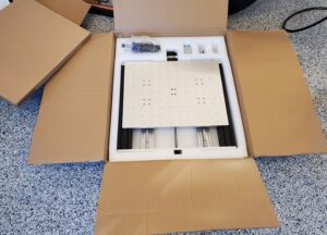
It arrives in a single large box, with 2 smaller boxes inside. Everything is packed custom foam. There were no dents, scratches, or missing parts.
Mechanical Assembly
As expected, there is a fair amount of assembly required. Plan on appx 4 hours. I won’t go into all the steps covered in the manual, but instead will focus on clarifications and recommendations on the steps that were found to be difficult or confusing.
Assembling the Gantry
The gantry assembly is the most tedious. There are a total of 16 T-slot nuts that have to be lined up with the gantry holes.
You are given an alignment tool to pre-position these with the right spacing. The other part of the tool is to set the gantry position in Y. It is best to position the nuts close to the final gantry position.
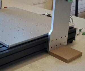
Once the nuts are in place, place the gantry on top of the MDF blocks, taking care not to bang any of the nuts out of place.
For the next step, I used the largest drill bit shank that would fit in the threaded holes of the nuts to perfectly align them, otherwise many of the bolts would not engage the threads.
Insert a bolt into each nut, working from the inside to the outside. Some if them can be difficult to engage, depending on the slop of the nut in the rail. A better system would have each set of 4 nuts in a carrier, with the right vertical and horizontal spacing. Once all are inserted, tighten them all down completely to be sure the threads are engaged (I found out the hard way).
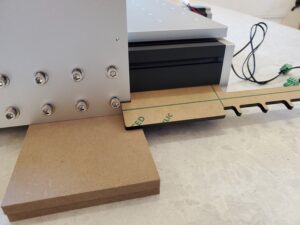
Then loosen all the bolts and position the gantry in place with the tool.
Assembling the Z Stage
The Z stage assembly is also a little unobvious. There are 2 rows with 6 T-slot nuts each.
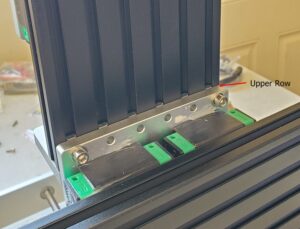
First secure the Z stage to the upper row of holes on the gantry X plate and the upper row of T-slot nuts as shown. Insert all 6 bolts loosely.
Now slide the Z assembly down and secure it to the bottom row of holes and T-slot nuts.
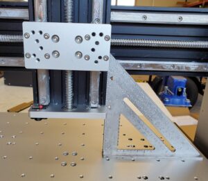
Once done, confirm the assembly is vertical relative to the table plate.
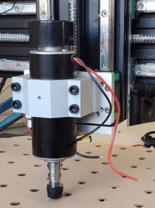
Installing the Spindle Motor
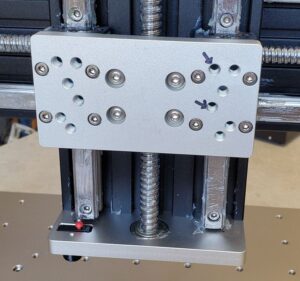
The Z stage plate should be oriented as shown. My manual illustrated it upside down, which is incorrect. The arrows indicate the mount points.
I needed to pry the spindle mount flexure slightly with a screwdriver in order to get the spindle to go in. Orient the wires to face the right hand side, where they will get connected later.
There were no instructions for the Z position of the spindle in the mount. I decided to lower the Z stage all the way and position it such that the collet could never impact the stage and spoilboard.
Complete Assembly
Complete the remainder of assembly, including the electrical harnessing. Make sure the connectors snap securely into the control unit.
Initial Testing
I did initial basic testing by connecting a tablet to the Anolex access point.
Use the Anolex GUI to move each axis and confirm the machine homes ok.
Note the MAC address for later by entering the following GCode command in the UI: $I
Connectivity
I did not want to deal with a Usb connection between the unit and a PC. I did not want to have a PC in the shop exposed to all the debris. Further, my preference is use headless VMs for all development and control.
Set it to be a wifi client.
Click the tab ESP3D
Station SSID: change from GRBL_ESP to your ssid. Click Set
Station Password: set the password and then click Set
Radio Mode: choose Client Station, then click Set
I gave it a static IP on the LAN.
Now you can browse to the Anolex GUI from any PC.
GCode Sender
The manual includes an example using Candle. In short, Candle is horrid. It is a QT app that needs to be installed on a PC, and the installation didn’t work. I wasted a lot of time getting it to work and only after creating a subdirectory “platforms” in the application directory and copying qwindows.dll there would it finally launch.
Upon realizing it could only communicate over USB I abandoned it.
After a fair amount of research into alternatives, I settled on Universal G-Code Sender (UGS). It supports connecting to the machine via TCP, Grbl controllers, Linux, and seems popular.
UGS Setup
After installing, launch the app. Add the Anolex machine by choosint Machine, Setup Wizard.
Connection driver: TCP
Firmware: GRBL
Host: enter the IP address of your machine. e.g. 10.0.0.99
Port: 23
When I click Connect, sometimes it could not connect to the controller, but after a couple of tries it succeeds. I think it chokes on the initial “ok” from the Anolex, when instead it is looking for the Grbl response which immediately follows.
Click Next and proceed to the wiring step.
Test the motors motors. It has Y checked as reversed, which I is correct.
Homing: shows -X, +Y, +Z. This indicates home is X to the left, Y stage all the way forward, Z stage all the way up.
Choose Try Homing. It does X, then Z, then Y.
Choose Finish.
Every time the Anolex is powered on, you will have to reconnect UGS, and it usually takes 2-3 attempts before it connects successfully.
Wrapup
Now proceed with your test cuts.