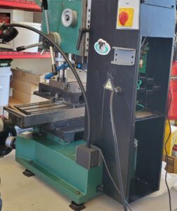
I finally got around to adding a digital position read-out (DRO) to my Grizzly 0463 mill. Up til now managing positions has been done manually…keeping track of wheel turns, which for more complicated parts is just too tedious and error prone.
It was clear going in that this would take significant chunk of time, and sure enough, it took approximately 50 hours for a 3 axis install. This includes the installation approach for each axis, the design and fab of parts, and installation. Each axis had it’s own challenges. I needed to design 5 different custom 3D printed parts, milla custom aluminum brack, and modify two of the included mounting brackets. Hopefully this post will help others avoid some of the pitfalls and save time coming up with a workable approach.
Part Selection
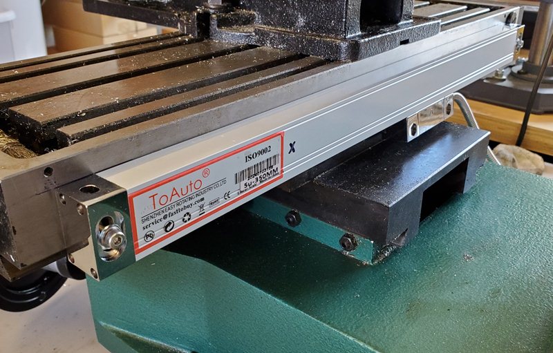
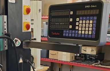
I had originally planned to create an ESP8266/Arduino based system, but with the general availability of affordable commercial units, I instead went with the TOAUTO 3 Axis Digital Readout Display. It is a complete 3 axis kit with scales, read heads, display, scale covers, and hardware. I was able to custom order optimal desired lengths for this mill, with X=350 mm, Y= 200 mm, and Z= 300 mm. You can order custom lengths to the nearest 50 mm. Also available on Amazon.
X Axis Approach & Installation
The design approach was surprisingly difficult. There are a number of considerations. There isn’t much vertical space for the cover, scale, and read head. The read head mount must be positioned to cover the full range of travel. The various mounting holes must be accessible with a drill and tap, including 2 holes for the scale cover, 2 for the scale, and 2 more for the read head mounting bracket. Given the incremental length limitations of 50 mm and available space on the X stage, the scale is somewhat shorter than the travel length. I wanted the travel limit all on the left side of the stage so I could install an X limit stop (else the read head will get crunched).
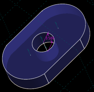
The holes for the cover were done first, to establish the position for the scale underneath. All mounting holes are drilled with a 3.3 mm bit and tapped with a blind tap for M4.
Install the cover, position the scale, and mark the mounting hole positions. Now drill and tap the two mounting holes for the scale.
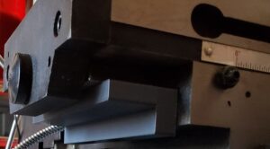
For mounting the scale, the read head unfortunately has the same width, so the scale needed to be mounted shimmed out to avoid the (fixed) read head rubbing on the X stage as it moved. I designed a bushing to set the right distance and ensure the scale lays flat.
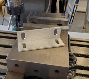
Next, a bracket for the read head was machined from aluminum angle.
Drive the X stage to the rightmost limit, position the bracket and mark the mounting holes on the Y stage.
Drill and tap the mounting holes
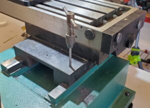
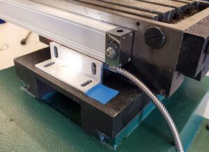
Now the scale can be mounted and leveled relative to the Y stage where read head mounts. Optionally use a dial indicator, but I found it works fine if level to 1 mm over the length of travel. Install the bracket and mount to the read head.
Connect the read head to the display, turn the display on and move the X stage over the entire range of travel to confirm reads correctly.
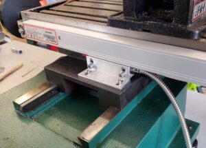
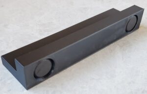
Next, a stop was needed to limit maximum X travel to keep the read head within range of the scale. The simple approach was a 3D printed block to mount underneath the X stage and attached with magnets.
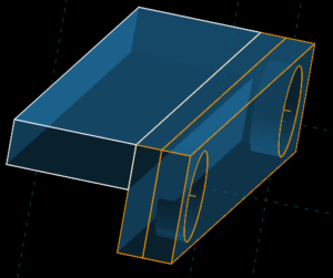
The 3D printed part with magnets glued into the two recesses.
The X stop installed on the stage.
Models for all custom 3D printed parts created for this project can be found at Printables.
Display Mount
The display is mounted on the right side and up high away from the mess that gets made during milling. Remove the rear cover and mount the bracket for the base of the arm.
There are zero instructions included with DRO kit. I found the mount of the bracket to the display unobvious, so here is how it is attached.
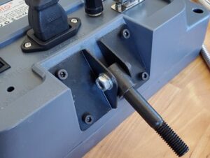
Assemble arm and attach.
Next Steps
Next up is the Y axis installation.