I have a growing number of microcontrollers deployed in my HomeLab. Many of these are located inside the home, in the open. I needed some kind of enclosure that looks nice. While there are vast quantities of prototype boxes, they are generally ugly, and don’t offer the right form factor. So I decided to design my own for 3D printing.
Design Requirements
The first objective was to have a vertical form factor, which would minimize shelf space, and fit on a window sill.
I wanted it to be modular, with separate parts for a base mount, board mount, and cover/enclosure. This would accommodate different electronic boards and associated sizes.
Base
The base would be the piece that gets mounted, or just sits on a surface (i.e. a stand). For mounting, it should allow screws or a magnet.
It would have a socket to allow different board mounts to be snapped in.
It would also provide a surface for the enclosure to attach to.
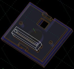
Board Adapter
The board adapter would be sized for the circuit board being used, allowing typically attachment with small screws with standoffs. Different adapters would be created for different circuit board sizes, e.g. for the solder breadboards I frequently use.
One end would have the male part of the snap-in fitting.
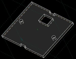
Cover
The cover hides the internal board. It also provides ventilation, especially important for resident temperature sensors.
I wanted tool-less attachment, so this would be a snap-fit as well. The idea is to squeeze the shell of the enclosure to release it from the base.
MCAD Design
Base
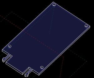
We’ll begin with the base, by far the most complex part.
Using SolveSpace, the initial layer was created.
This provides the screw mount holes and the entry point for a usb cable for powering the board.
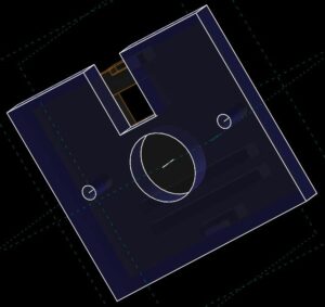
A layer was added below to incorporate a recessed area for a magnet and further build out the cable routing.
Layers were added on the top to include sockets for the board adapter and enclosure.
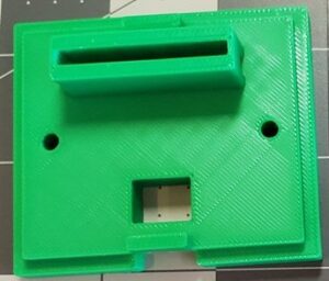
The printed base.
Board Adapter
The board adaptor shown here is designed for the CircuitSetup solderable breadboard.
Holes are provided for M4 screws.
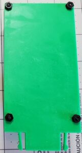
The printed adapter.
Cover
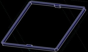
The base layer incorporates the tabs for snap fitting the enclosure to the base.
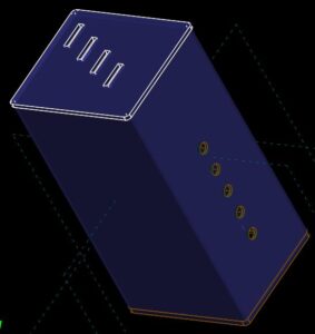
Ventilation provided on both the top and side.
The design files can be found at Thingiverse.
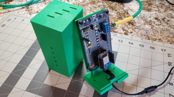
Completed Examples

The assembly, with board carrier inserted into base, and slip on cover.
![]()
Assembled, with clear cover.