I have a swimming pool. Long ago I made the move to manage it myself as the services to take care of it were the equivalent of gardener mow & blow. It does take time, and I’m trying to automate as much of the effort as I can.
One challenge, especially in the summertime, is to maintain the water at an appropriate level. The water fill is connected to a sprinkler valve on a timer, which adds water daily, but it’s guess work at best. Evaporation can be huge when the cover is left off. Simply overfilling drives up the water bill. And the water feed comes off of a water softener to minimize calcium buildup, so I wanted to minimize water softener recharges too.
I’ve already had the unfortunate event of the water level falling below minimum and burning up the main pump.
The first phase, described here, is to install a simple water level sensor that integrates into my Home Assistant environment, to notify if the water level gets too low.
Sensor Approach
I wanted the setup to be hidden from view as much as possible, primarily for aesthetic reasons.
It should be safe, not introduce a trip hazard or electrical safety issue.
Being outdoors, it needs to survive the weather, including sun and rain.
Both ultrasound and mechanical sensors were considered. Ultrasound offers good resolution with fine measurement for a spectrum of water level readings. But it has a couple of major issues. First, the minimum reading distance is approximately 8-10 inches. My preference was to install the unit inside the skimmer basket area, out of sight and fully enclosed and protected from weather. This was not an option as the water level was only 6 inches below the cover. The second issue is the cable length from the ultrasonic transducer head is limited to approximately 8 feet. The goal is to place all the electronics in the pool shed some 15 feet away.
The other option was a mechanical float sensor. These use a reed switch in the post, with a magnet in the float. Dual float sensors are available, which would provide 3 levels of information – low, fill, and full. It has the same downsides as all things mechanical, including the potential to get gummed up by algae, and failure of the reed switches over time. But it would fit inside the skimmer basket area, and cabling would reach the shed, so I opted for this approach.
Sensor Selection
The overall length and separation of floats were key considerations. Preference was given to stainless steel (vs plastic) units for resistance to chlorinated water.
After extensive research, the Aopin Water Level Sensor Switch model ZS12010-2 was selected.

I could not find a unit long enough, but this one met the sweet spot for range. After experimentation, the float was found to move to the up position once water was 2/3 of the way from the bottom of the float. As measured from the lowest position (lowest float down) to highest position (upper float up), this provides a range of 2.2″.
Sensor Mount Design
The float sensor would be mounted onto the skimmer cover. I bought another cover for building the prototype. This distance from the bottom of the cover to the desired maximum water level was about 6″, so a mount extension would be needed.
Using SolveSpace MCAD, a hollow post was designed and 3D printed.

The design files can be found at Thingiverse.
For mounting, a hole is drilled in the skimmer cover and the tube inserted and screwed to the cover with 3mm machine screws.

The tube inside diameter was sized for tapping with a 10 mm tap.
Route the wires through the tube and screw the float sensor onto the extension post.

One downside to this design is that once mounted, it would be difficult to replace the sensor as the wire connections would have to be done over again. Ideally this post would have a slotted opening in the tube so that the sensor wiring could be routed separately, but that is beyond my SolveSpace skills at this time.
Electronics Design
A Wemos D1 mini was used as the microcontroller. I used the CircuitSetup solderable breadboard for final assembly. You can also find them on Amazon.

There are screw terminal mounts for the float sensor wiring. The two pairs of wires from the float sensor were soldered to a waterproof pigtail. I used the BTF-LIGHTING 4 Pin Electrical Connector.

An extension cable was made from an old CAT cable, with the mating pigtail on one end and bare wires on the other end for attaching to the screw terminals.
Each float reed switch is wired to ground on one side and a data input with 10K pullup resistor to 3.3v on the other side.
The circuit board is mounted to a custom 3D printed board carrier and snap-fit base. I’ll document this in a future post.
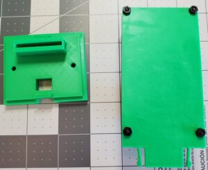
The assembly, with board carrier inserted into base, and slip on cover.

Software Design
The portion of the software worth discussion is the debounce of each of the floats on the sensor. The floats are subject to wave action and subsequent false triggers, so any change in state is subject to a minimum stability period before the state machine allows a change to the new state.
State information is communicated to an mqtt broker, and monitored by my Home Assistant. The two floats are combined by the software and reported as a single entity with both numeric state and a string format state.
The code can be found on Github.
Integrating with Home Assistant
Create an mqtt sensor.
# ======== Water Level Sensor ========
# mqtt reporting by the water level sensor.
# Publishes a Json data payload:
# Referenced as sensor.pool_water_level in template sensors.
- platform: mqtt
  # name: defines how this will be reference, e.g. by template sensor definition. Of the form 'sensor.thename'
  name: "pool_water_level"

  # state_topic - The mqtt topic subscribed to receive sensor values from the device.
  state_topic: "device/pool/waterlevelhigh"

  # The MQTT topic subscribed to receive a JSON dictionary payload and then set as sensor attributes.
  # The dictionary of sensor attributes can be parsed with separately defined template sensors.
  json_attributes_topic: "device/pool/waterlevelhigh"

  # expire_after (optional) - #seconds after the sensor’s state expires.
  # If it’s not updated, after expiry, the sensor’s state becomes unavailable. 15 minutes= 900 sec.
  expire_after: 900

  # QOS - 0 (default)
  qos: 1
Next, create a template sensor for extracting the json payload values.
# ======== Water Level Sensor ========
# References the mqtt sensor 'pool_water_level'
# mqtt: {"state":"on","FloatStateInt":3,"FloatStateStr":"Full","StateChangeAgeSec":10468,"StateChangeRawAgeSec":10528}
# Extracts the json field FloatStateStr and Outputs it as State.
- platform: template
  sensors:
    # Water Level Template Sensor
    pool_water_level_state_ts:
      friendly_name: 'Water Level Sensor State'

      # state_attr('sensor.name', 'JsonFieldName')
      # Low|Fill|Full|Invalid. Shows as 'None' until initial read.
      value_template: "{{ state_attr('sensor.pool_water_level', 'FloatStateStr') }}"
Results
I like how the whole unit is out of sight. To empty the skimmer basket, when the cover is removed, flip it upside down to prevent a low water level false alarm.
The entire cost of hardware is under $100.
We’ll see how the sensor holds up over time.
For next steps, it makes sense to utilize the readings to drive the water fill schedule.